Author: Tim Alatorre

  • Revit Families 103 – Formula Basics


    Update: 4/12/11 for Revit 2012 and added more examples.

    I love formulas, they let you do some really fun things.  The formula I mentioned in my last post calculates the overall width of a family taking into account if the family has one or two loops toggled to be visible.  Formulas let you create a family that is truly flexible and has a lot of built in intelligence and a few safeguards.  They can also make using the family a lot easier to use by maintaining relationships between elements or calculating details about the family like area, volume, etc.

    I do some pretty advanced stuff with formulas, but we need to get the basics under our belt first.  Most of this post is from the Revit Help files.  To save you the trouble of looking it up, I’m putting it here.

    Keep in mind that Revit is aware of units.  So to avoid getting an inconsistent units error remember to divide and multiply when appropriate.
    For example, these are correct formula:

    (Length_A * Length_B) = Area_C
    (Length_A * Length_B)/1 = Length_C

    Basic opperators:

    + Add: 15′ + 0′  6″ + Length sin Sine: sin(75)
    Subtract: 1′ 2″ – Width cos Cosine: cos(75)
    * Multiply: Length * Width tan Tangent: tan(75)
    / Divide: Length / 8 asin Arcsine: asin(75)
    ^ Exponent: x^y, x raised to the y power acos Arccosine: acos(75)
    log Logarithm: log (100) atan Arctangent: atan(75)
    sqrt Square root: sqrt(64), square root of 64 = 8
    exp E raised to an x power: exp(2)
    abs Absolute Value: abs(-2), will return 2
    pi pi: pi() * (Radius ^ 2), the formula for Circumference

    Conditional Statements

    A conditional statement uses this structure:

    IF (<condition>, <result-if-true>, <result-if-false>)

    This means that the values entered for the parameter depend on whether the condition is satisfied (true) or not satisfied (false). If the condition is true, the software returns the true value. If the condition is false, it returns the false value.

    Supported Conditional Operators

    < Less Than
    > Greater Than
    = Equal to
    / Divide: Length / 8
    AND Both statements are true
    OR One of the statements is true
    NOT Statement is false

    Conditional statements can contain numeric values, numeric parameter names, and Yes/No parameters.

    Currently, <= and >= are not implemented. To express such a comparison, you can use a logical NOT. For example, a<=b can be entered as NOT(a>b).  For more information see “Revit Families 402 – Greater Than or Equal To

    Sample Conditional Statements

    Simple IF Statement
    IF (Length < 30′, 2′ 6″, 4′)

    Formula That Returns Strings
    IF (Length > 30′, “This thing is tall”, “This thing is short”)

    Using logical AND
    IF ( AND (x = 1 , y = 2), 8 , 3 )

    This will return <true> if both x=1 and y=2, else <false>

    Using logical OR
    IF ( OR ( A = 1 , B = 3 ) , 8 , 3 )

    This will return <true> if either A=1 or B=3, else <false>

    Nested IF statements
    IF ( Length < 10′ , 1′ , IF ( Length < 20′ , 2′ , IF ( Length < 30′ , 3′ , 4′ ) ) )

    Returns 1′-0″ if Length<10′-0″, 2′-0″ if Length<20′-0″, 3′-0″ if Length<30′-0″ and 4′-0″ if Length>30′-0″

    IF with Yes/No condition
    Length > 10
    (Note that both the condition and the results are implied.)

    Returns checked box <true> if Length > 10

    NOT with Yes/No condition
    not(myCheckbox)

    Returns checked box (<true>) of Yes/No parameter “myCheckbox” is unchecked, and it returns <false> if “myCheckbox” is checked.

    Rounding

    Prior to Revit 2012 the only way to round numbers was to pass a number through an integer parameter.  The integer parameter always rounds to the nearest whole number with the standard mathematical rounding rules of:

    Down -> for fractions of 0.0 to 0.49 and -0.5 to -0.99
    Up -> for fractions of 0.05 to 0.99 and -0.49 to 0.0

    As of Revit 2012 we now have three additional functions to use!!

    Note that “x” is unit-less

    Round(x)
    Rounds to the nearest whole number per the standard rules mentioned above.

    round (1.1) = 1
    round (1.5) = 2
    round (1.7) = 2

    round (-1.1) = 1
    round (-1.5) = 1
    round (-1.7) = 2

    Roundup(x)
    Rounds to the largest whole number greater than or equal to “x”.

    round (1.0) = 1
    round (1.5) = 2
    round (1.6) = 2

    round (-1.0) = 1
    round (-1.5) = 1
    round (-1.6) = 1

    Rounddown(x)
    Rounds to the smallest whole number less than or equal to “x”.

    round (1.0) = 1
    round (1.5) = 1
    round (1.6) = 1

    round (-1.0) = 1
    round (-1.5) = 2
    round (-1.6) = 2

    Some Extra Stuff

    • Revit allows you to use integers, decimals, fractional values, and parameter names in formulas.  You can enter dimensions in feet and inches just like you do in dimension strings.  Remember that parameter names are case sensitive.
    • You can enter a value in a formula essentially locking it across all types.  This is an alternative to locking the dimension in the model.
    • Instance and Type parameters can not be used in the same formula.
    • It’s a good idea to not name your parameters with any of the mathematical operators in this list.
  • Revit Families 302 – Naming and Grouping Parameters

    I started a post a couple weeks ago on tips for creating families in Revit but I didn’t get very far.   Our friends over at Inside the Factory are more disciplined bloggers than I and beat me to it. Erik Egbertson put together a great post of Family Editor Tips.  He talks about flexing a family, placing Constraints Consistently, not over constraining, avoiding chaining references, shortcuts to duplicating elements, shortcuts to creating dimensions, labeling shortcuts, and a couple other tips.

    Initial Setup and Naming of Family Parameters

    One thing that Eric didn’t cover in too much depth was naming and grouping of parameters.  I also use Eric’s programming syntax method for naming parameters except I usually capitalize the first letter.  It doesn’t make much difference really, I just like the look of it in my parameter list.  For example, “WindowTrimWidth” instead of “windowTrimWidth”.  Although Revit supports parameter names with spaces, I think having your parameters as one “word” makes writing formulas easier.

    The first thing I do when setting up a new family is place all of my reference planes, dimensions and parameters.  I flex the model with the reference planes and make sure it works.  If it does then I’ll start modeling the geometry.

    When I first add parameters I don’t write out the whole name for parameters that I know will involve some calculations.   Sometimes formulas can become quite complex:

    if(and(LoopOne, LoopTwo), DepthDefault, if(or(LoopOne, LoopTwo),DepthDefault- DepthBikeLoop, Diameter))

    Make one error in typing this out and you have a hard time debugging it.  I start with naming my parameters with shortened names like LO, LT, DD, etc.  This makes the structure easier to see.

    if(and(LO, LT), DD, if(or(LO, LT), DD – DBL, D))

    Once I know everything is working I rename the parameters and they are automatically updated in my formulas.

    Grouping of Family Parameters

    Currently Revit only allows us to categorize parameters in a set list.

    • Analysis Results
    • Analytical Model
    • Constraints
    • Construction
    • Dimensions
    • Electrical
    • Electrical – Lighting
    • Electrical – Loads
    • Electrical Engineering
    • Energy Analysis
    • Fire Protection
    • Graphics
    • Green Building Properties
    • Identiy Data
    • IFC Parameters
    • Layers
    • Materials and Finishes
    • Mechanical
    • Mechanical – Airflow
    • Mechanical – Loads
    • Model Properties
    • Other
    • Phasing
    • Photometrics
    • Plumbing
    • Rebar Set
    • Slab Shape Edit
    • Structural
    • Structural Analysis
    • Text
    • Title Text
    Analysis Results
    Analytical Model
    Constraints
    Construction
    Dimensions
    Electrical
    Electrical – Lighting
    Electrical – Loads
    Electrical Engineering
    Energy Analysis
    Fire Protection
    Graphics
    Green Building Properties
    Identiy Data
    IFC Parameters
    Layers
    Materials and Finishes
    Mechanical
    Mechanical – Airflow
    Mechanical – Loads
    Model Properties
    Other
    Phasing
    Photometrics
    Plumbing
    Rebar Set
    Slab Shape Edit
    Structural
    Structural Analysis
    Text
    Title Text

    I’m glad that Revit doesn’t let us customize this list, it would just complicate things even more.  Eric reminds us to “choose a pertinent parameter group for your parameters,” but what does that mean?  Really, it depends on your office.  I would recommend creating a standard.

    I discourage the use of the “Other” category because it ends up being a trash bin holding everything.  “Dimensions” is obvious, but I only put parameters in this group that are relevant to the user of the family.  I use “Analytical Model” for any behind the scenes calculations or dimensions that the user of the model doesn’t need to bother with; unit conversions, dimension calculations to keep the model from breaking, etc.  I have also seen “Model Properties” used for this.  If I have toggles for the visibility of different components I put those under “Construction“, if I have a toggle for something that is graphical only, like in an annotation family, I put that under “Graphics“.

    Tomorrow we will look at using formulas in families.

  • Revit Families 301 – The Struggle of the BIM Manager

    frustratedOkay folks, this is a 300 series course.  We’re not messing around anymore.  Families are one of the most powerful and dangerous things in Revit and I think they deserve some discussion.

    One of the greatest challenges I have as a BIM manager is the management of Revit Families.  I’ve tried a number of different approaches over the years and I have yet to find one that I like 100%.  I’ve always worked to establish a set of approved office standard families and have had an internal review and approval process.  The standard families account for probably 90% of the families needed on a standard project, the problem lies in the 10% of custom families or the 90% customization needed when we do a new building type we haven’t done before.

    In the early days I mistakenly thought that if I left modelers in the dark on how to edit families they wouldn’t do it.  I could train a couple of key people to do all the family modeling.  As you may expect, that didn’t work for long.  People didn’t want to go through the hassle of having someone else make and edit a family, especially when they are under pressure from a project manager.  They created families and edited the families themselves but because they didn’t know what they were doing they created families that couldn’t be reused without extensive reworking.  Usually they spent an extensive amount of time going in circles or not enough time to do something right the first time.  Days later when they would go to make a dimension change the family would break.

    The other strategy is train everyone on editing families and hope for the best.  This requires a lot more work for the BIM manager, training, supervision, review, etc.  However the entire staff ends up more educated and because they know the inner workings of the family they can use them more effectively in the building model.

    In general the people working on your models are intelligent, want to learn, and want to do a good job.  In the long run teaching them how to create and edit families goes a lot further and will save you time.

  • Revit Mental Ray Renderings in Design Development

    In the “old” days of architecture, the Architect, a skilled artist in his own right, would sketch a perspective view of a room or the building as a whole early on in design process.  As the concepts and visions evolved these sketches were revised or redrawn numerous times.   This combined with a mountain of floor plans sketched on trace paper allowed the client to have a rough idea of what the building would look like at many points in the design process.

    Fast forward to the computer age and the AutoCad revolution in the 90’s.  During the last decade architects have relied less and less on perspectives and more on the more easily produced plans and elevations.  Renderings were only done once the design was nearing completion because the cost of producing high quality computer graphics was prohibitive to a multitude of revisions.  Our clients, more often than not, were expected to interpret the floor plans, site plans, and elevations.  Often times the draftsmen themselves didn’t fully understand how the building was going to look, let alone how all the pieces worked together in three dimensional space.

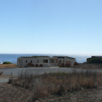
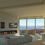
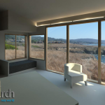
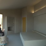
    Today we have Revit with the easy to use Mental Ray rendering engine and a 3d model of the building at our fingertips at all points in the design process.  Below are a few shots of a design I’ve been working on.  The project has gone through numerous revisions and it’s relatively easy to create a new rendering after every change, not to mention the almost constant use of the non rendered 3d model.  Since all of the topo and site data are in the Revit model I can place my camera at the exact location where the real world contextual photographs were taken resulting in some fairly accurate results in a short amount of time.  In house, on the fly renderings have once again become a cost effective part of the design work flow!

  • Revit Tip: Easy Wall Poche

    This is the first of what is hopefully many more Revit Tips to come.  Something that I’ve seen in some projects I’ve worked on lately is using filled regions to poché walls and floors in section views.  DON’T DO THIS! Besides taking a large amount of time to initially create, filled regions are not going to update as you add or remove walls, windows, etc.  So how do you poché your walls?  Easy.

    Default Revit Sections Are Flat!
    Default Revit Sections Are Flat!

    There are two tools that you will use to make this happen, Visibility/Graphic Overrides and the Join Tool.

    I think the reason that you would try to used filled regions to poché walls is because you don’t fully understand how Revit displays objects.  Revit uses a hierarchy of graphic settings to determine what to display.

    On the most general level are the project’s Object Styles.  You reach these by going to Manage -> Settings -> Object Styles.  I could write a number of essays on what you can do here, but right now we will just focus on the Walls category.  The main walls category by default has 3 sub-categories.  For these 4 category/sub-categories you can set the line weights/color/pattern for projection and cut views as well as the default material.  This is where we could bump up the line weight for cut walls to make our elevations read clearer.

    (more…)